4.1 The Shader
This project heavily relies on GLSL (OpenGL Shading Language) for its rendering and interactivity. In this documentation, we will cover the essential aspects of the shader code. If you are new to shaders and would like to learn more, I recommend checking out the Book of shaders for a comprehensive introduction.
If you have scouted around the <Buffer/> component, you may have noticed that there a lot of elements orchestrating it. Let’s try to understand it before diving into the code.
The component is named “Buffer” because it serves as a temporary container of information. In the context of 3D objects, each object has various properties such as materials, position, rotation, scale, and opacity. However, in this discussion, we will focus on the object’s geometry.
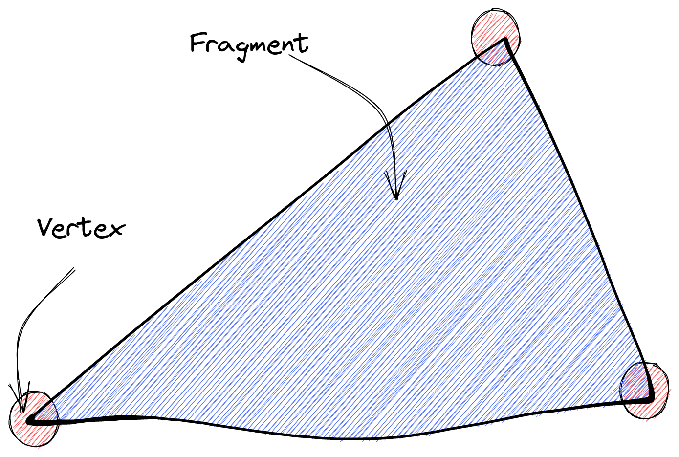
The geometry of a 3D object consists of two key elements: vertices and fragments.
-
Vertices are 3D points in space. They do not occupy physical space themselves but serve as connectors for the fragments.
-
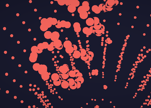
Fragments connect the vertices and are responsible for painting pixels on the screen. In this component, the emphasis is on the vertices, which are represented as particles or small dots in space. These particles are not directly connected to each other like traditional geometry; instead, they exist independently.
Now let’s explore the code and dive deeper into the implementation of the shader.
The vertices are saved in a Float32Array, which saves thousands of numbers that are later decoded into what you see, in an attribute called position.
In our implementation, the <Buffer/> component represents not just a single object, but rather a collection of objects that change over time. To achieve this, we utilize a box-like structure where we define different positions for various objects such as a lightbulb, a chess piece, a box, etc. These positions are then interchanged dynamically.
Within the shader code, we declare attributes to represent these different geometries, like so:
attribute vec3 position; // Box geometry
attribute vec3 position2; // Random cloud geometry
attribute vec3 position3; // Rocket geometry
attribute vec3 position4; // Lightbulb geometry
attribute vec3 position5; // Chess piece
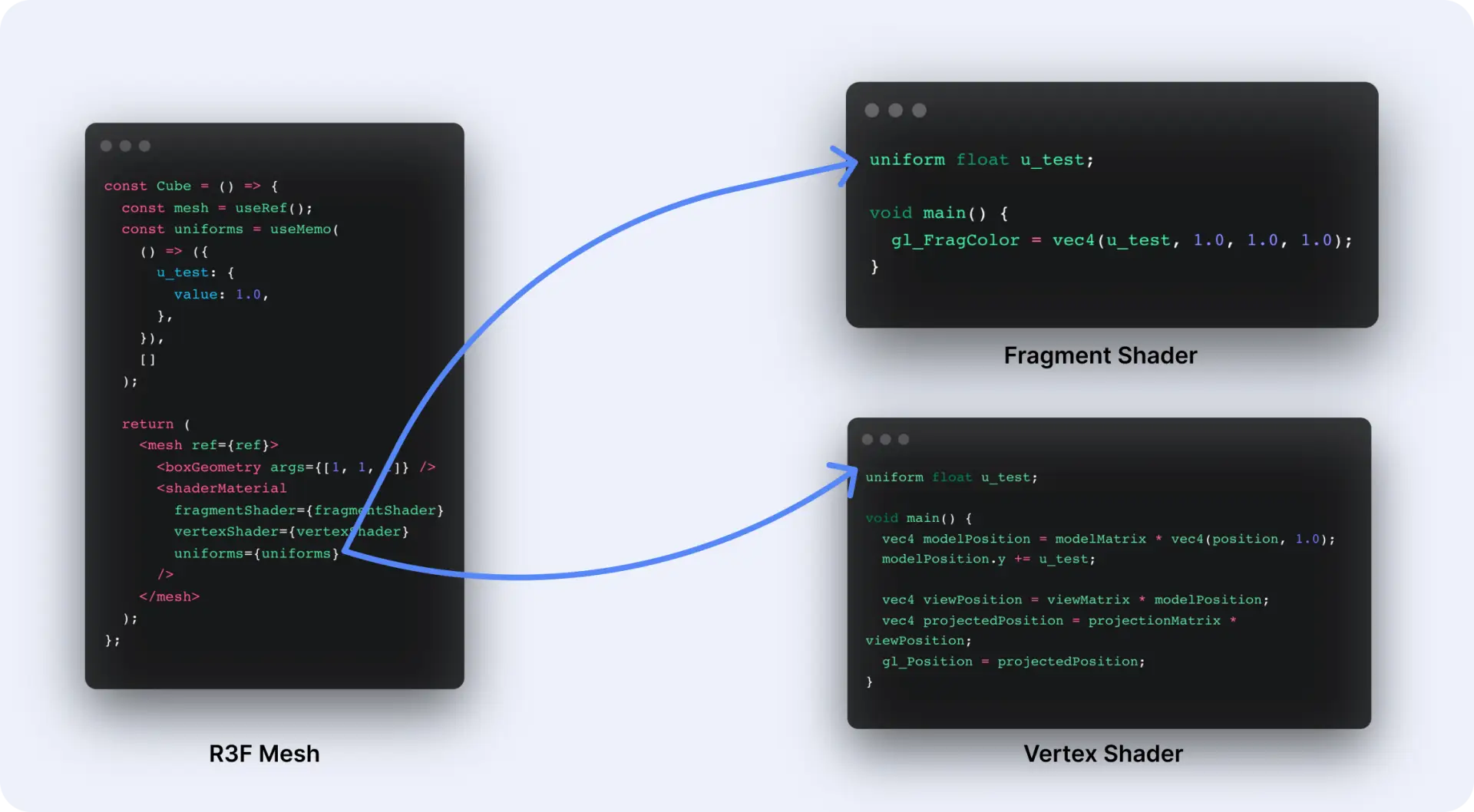
...The purpose of these attributes is to allow us to change the geometries of the objects dynamically. Additionally, we also want to modify other aspects of the shader, such as particle size, color, transparency, and speed. To achieve this, we use uniforms, which can be modified from our TSX code as usual.
It’s important to note that a
uniformserves as a bridge between the GLSL code and the TSX code. They act as parameters that are passed into the shader and computed to create the visual effects we observe on the screen.
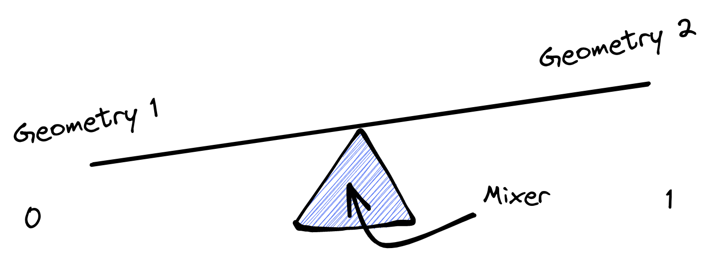
These uniforms are then used to interpolate between the different geometries using the mix GLSL function:
//Cycles between geometries
vec3 switchGeometry3 = mix(position5, position, state3);
vec3 switchGeometry2 = mix(position4, switchGeometry3, state2);
vec3 switchGeometry1 = mix(position3, switchGeometry2, state1);
vec3 switchGeometry = mix(position2, switchGeometry1, randomState);
Think of the mix function as a scale. The first two parameters are both sides of the scale. The third value (a number between 0 and 1) is what determines how left or how right will the balance end up going.
To add some idle animations to the geometries and make them look organic and alive, we utilize a simple sinus animation and incorporate Perlin noise using Stefan Gustavson’s Perlin noise function.
The sinus animation creates an up-and-down movement effect by applying the sin function to the x coordinate of the model position, multiplied by a factor of 5, and the current time multiplied by 2.5. This value is then multiplied by 0.02 to control the magnitude of the animation.
The Perlin noise animation is achieved by using the cnoise function with the modelPosition.yz (excluding the x coordinate) and the current time multiplied by 0.5. The resulting noise is later toned down by bein multiplied by 0.05.
To combine these two animations, we use the mix function, which blends the sinus animation and the Perlin noise animation together with a balance of 0.5. The resulting value is stored in the idleAnimation variable.
//IdleAnimation
float sinusAnimation = sin(modelPosition.x * 5.0 + time*2.5) * 0.02;
float perlinNoiseAnimation = cnoise(vec3(modelPosition.yz, time*0.5))*0.05;
float idleAnimation = mix(sinusAnimation,perlinNoiseAnimation, 0.5);
In the fragment shader, the main goal is to determine the color and transparency of the pixels. The bufferColor uniform represents the color of the particles, and the transparencyState uniform controls the transparency.
The particles are made to appear round by creating circles in the middle of each particle. This is achieved by calculating the distance of the current fragment coordinate from the center of the particle and comparing it to a threshold value of 0.5. If the distance is less than 0.5, the fragment is inside the circle and is assigned a value of 1; otherwise, it is outside the circle and is assigned a value of 0. This value is then multiplied by the transparencyState to control the overall transparency of the particle.
uniform vec3 bufferColor;
uniform float transparencyState;

void main()
{
    //make particles round
    vec2 xy = gl_PointCoord.xy - vec2(0.5);
    float ll = length(xy);
    float round = step(ll, 0.5);
    float finalAlpha = round;
    finalAlpha *= transparencyState;

    gl_FragColor = vec4(bufferColor, finalAlpha);
}
It’s important to note that transparency in the GLSL world is not truly achievable due to the limitations of rendering techniques. In this implementation, each particle is treated as a single vertex, resulting in square particles with circles in the middle to create the impression of transparency: